
Monday - Friday: 9am - 6pm.
Saturday: 10am - 2pm.
Sunday & Public Holiday: Closed.
Buy online 24/7 or walk-in to our store, our friendly team is always ready to serve you :)
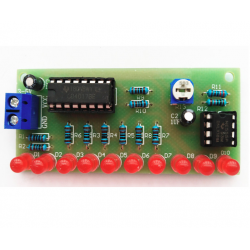

Note: Self assembly required - open the package & assemble the kit as the picture shown.
Kit parameters:
Power supply voltage: DC 3-5V (recommended voltage), actual measurement can be 2.5-8.0V
PCB size: 7.3*3.2mm
Function play:
After power on, the 10 LEDs will light up from left to right, showing the state of running water lights.
This kit can display the NE555 timing and CD4017 counting functions very intuitively. It is a starter kit
for learning timers, counters, dividers, and lantern controllers. At the same time, the kit has good effects,
is very interesting and practical, and is also the preferred material for beginners
to get started
Circuit principle:
This kit is mainly composed of a clock generation circuit and a decimal counter circuit.
It is a self-excited multivibrator with NE555 as the core. C1 is the bias supply bypass capacitor.
The power supply charges the capacitor C2 through R11, R12, and R13. When C2 just starts to charge,
the 2 pin of NE555 is still in Low level,
so the output pin 3 is high. When the power is charged to C2 through R11, R12, R13 to 2/3 of the
power supply voltage, the level of the output pin 3 changes from high to low, and the internal discharge
tube of NE555 is turned on. , Capacitor C2 is discharged through R13, R12, and pin 7 of NE555, until the
voltage across C2 is lower than 1/3 of the power supply voltage, the level of pin 3 of NE555 changes from
low to high again. C2 is charged again, This cycle forms an oscillation. The charging time is: 0.695(R11+R12+R13)C2,
and the discharging time is: 0.695(R13+R12)C2. Adjusting R13 can control the output frequency of the oscillator.
The clock oscillation signal of NE555 is continuously added to pin 14 of CD4017. 10 LEDs are connected to the 10
output terminals of the CD4017. When the 10 output terminals of the CD4017 generate high levels in turn under the
action of the clock signal, D1--D10 will be lit in turn to form a water lamp effect. Adjust R13 to adjust the flow
speed of LED lights