Monday - Friday: 9am - 6pm.
Saturday: 10am - 2pm.
Sunday & Public Holiday: Closed.
Buy online 24/7 or walk-in to our store, our friendly team is always ready to serve you :)
The MAX7219 is an integrated serial input / output common cathode display driver that connects a microprocessor to an 8 -digit, 7- segment digital LED display. It can also be connected to a bar graph display or 64 independent LEDs. It includes an on-chip B- type BCD encoder, multi-channel scanning loop, segment driver, and an 8*8 static RAM to store each data. There is only one external register used to set the segment current of each LED .
A convenient four-wire serial interface connects to all common microprocessors. Each data can be addressed and updated without rewriting the entire display. The MAX7219 also allows the user to choose whether to encode or not encode each piece of data.
The entire device contains a 150μA low-power shutdown mode, analog and digital brightness controls, a scan limit register allowing the user to display 1-8 bits of data, and a detection mode that lights all LEDs .
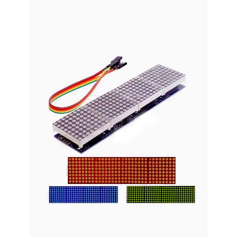
Only 3 IO ports are needed to drive 1 dot matrix! No flicker during dot matrix display! Support cascade!
Module parameters:
1. A single module can drive an 8*8 common cathode dot matrix
2.Module working voltage: 5V
3. Module size : 12.8cm long x 3.2cm wide x 1.3cm high
4. With 64 fixing screw holes, hole diameter 3mm
5. The module has input and output interfaces and supports cascading of multiple modules.
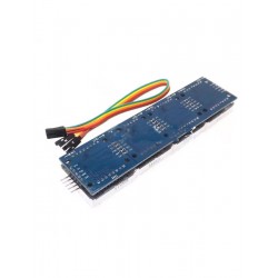
Wiring instructions:
1. The left side of the module is the input port, and the right side is the output port.
2. When controlling a single module, you only need to connect the input port to the CPU
3. When multiple modules are cascaded, the input terminal of the first module is connected to the CPU , the output terminal is connected to the input terminal of the second module, the output terminal of the second module is connected to the input terminal of the third module, and so on . ..
Take the 51 microcontroller as an example:
VCC → 5V
GND → GND
DIN → P2.2
CS → P2.1
CLK → P2.0